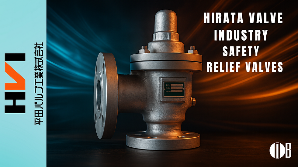
HVI Reliable Safety Relief Valves by Nichiboku Ltd.
- Luis Alberto Fing

- Sep 4
- 2 min read
Welcome to Nichiboku's industrial Blog
Introduction
In industrial systems where safety and efficiency are critical, pressure control cannot be compromised. HVI Reliable Safety Relief Valves deliver trusted performance in protecting boilers, pipelines, compressors, and liquid process systems. With precision Japanese engineering, these valves ensure reliable overpressure protection across air, gas, steam, and liquid applications.

Technical Advantages of HVI Reliable Safety Relief Valves
Built for demanding environments, HVI safety relief valves combine robust construction with reliable functionality. Designed for direct-acting, spring-loaded operation, they provide fast actuation, stable reseating, and long service life.
Key Benefits of HVI Safety Relief Valves
Multimedia versatility: Suitable for gases, steam, and liquids.
Fast and precise response: Quick opening when set pressure is reached; tight shut-off after relief.
Flexible configurations: Wide range of materials, seat types, and JIS flanged end connections.
Durable build: Precision-machined internals for repeatable performance.
Design & Engineering Excellence
HVI safety relief valves are engineered with stainless-steel internals, corrosion-resistant options, and precision-guided discs to ensure stable lifting and minimal chatter. Available in carbon steel, stainless steel, or cast iron, these valves adapt to a wide variety of plant requirements.
Range & Connections
Parameter | Range / Options* |
Nominal size | 8A – 250A (varies by valve type) |
Body material | Carbon steel / Stainless steel / Cast iron |
Media | Air, gases, steam, liquids |
Action | Spring-loaded, direct acting |
Seat | Metal or soft-seat options (per model) |
Ends | Flanged; JIS standards typical (others on request) |
*Exact limits (pressure/temperature classes, leakage class, blowdown range, capacity coefficients) depend on the specific model and configuration.
Example of Safety Valve Piping in Process Systems
Understanding the placement of vacuum and pressure safety valves is crucial for ensuring proper system design and operation. Below is a visual example of a typical safety valve piping layout.

Typical Applications
Boilers and steam systems
Air and gas receivers
Compressors and pumps
Heat exchangers and storage tanks
General process pipelines
Optimize Your Safety System
When specifying an HVI relief valve, important parameters include set pressure, required relieving capacity, medium type, body and trim material, and installation orientation. Nichiboku Ltd. provides expert support to help you select the ideal valve configuration for your plant’s safety requirements.
Contact Nichiboku Technical Support
Connect with Nichiboku's expert support team to explore tailored safety valve solutions for your application.📩 Nichiboku Ltd. – www.nichiboku.com📞 Contact us to request specifications or schedule a consultation with our technical team
.png)


Comments